Connecting the Hardware

Materials

  • AVR Microcontroller (ATmega328p)

  • Rotary Encoder

  • Two 10 kΩ resistors

  • Two 100 nF capacitors

Schematic

Connect the rotary encoder as shown below.

The microcontroller pins you connect to should agree with rotenc.c. I used PCINT8 (PC0) and PCINT9 (PC1) for signals A and B, respectively. (Pins C and D aren’t connected, since my rotary encoder didn’t have a switch.)

Rotary Encoder Schematic

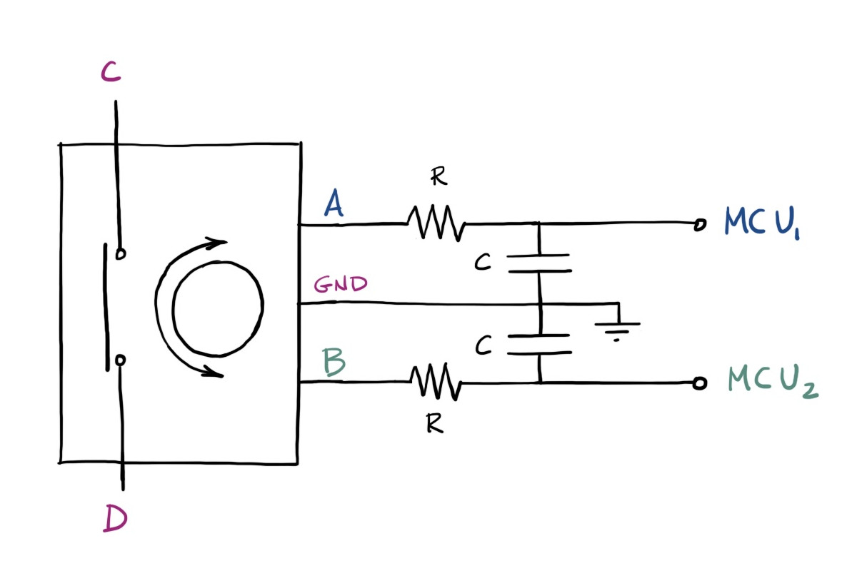
Both microcontroller pins should be enabled as input with an internal pull-up resistor.

Hardware Debouncing

A low-pass filter is used to smooth out any jitters that might occur as the rotary encoder is turned. This explains why pins A and B aren’t connected directly to the microcontroller.

The particular values of R and C may need to be tweaked if you plan to spin your rotary encoder really fast. For R = 10 kΩ and C = 100 nF, the cutoff frequency for the low-pass filter is about 160 Hz.

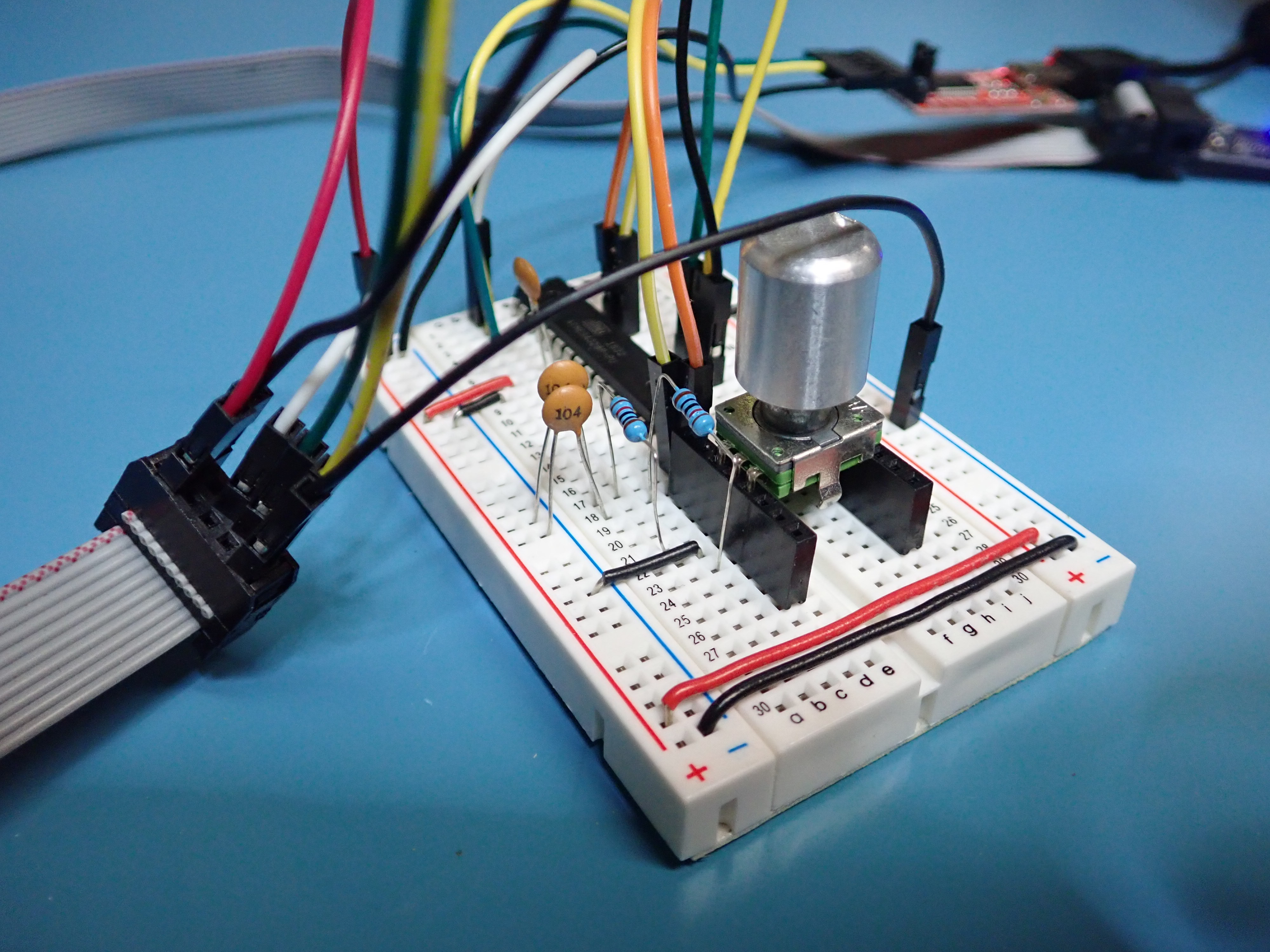
Here is what it looks like on my breadboard with a programmer and FTDI Serial-USB cable attached.

Rotary Encoder Breadboard