About Rotary Encoders
A rotary encoder looks like a potentiometer, with a rotating shaft and three output pins, but it turns indefinitely in either direction. The outputs tell you which direction the encoder is rotating.
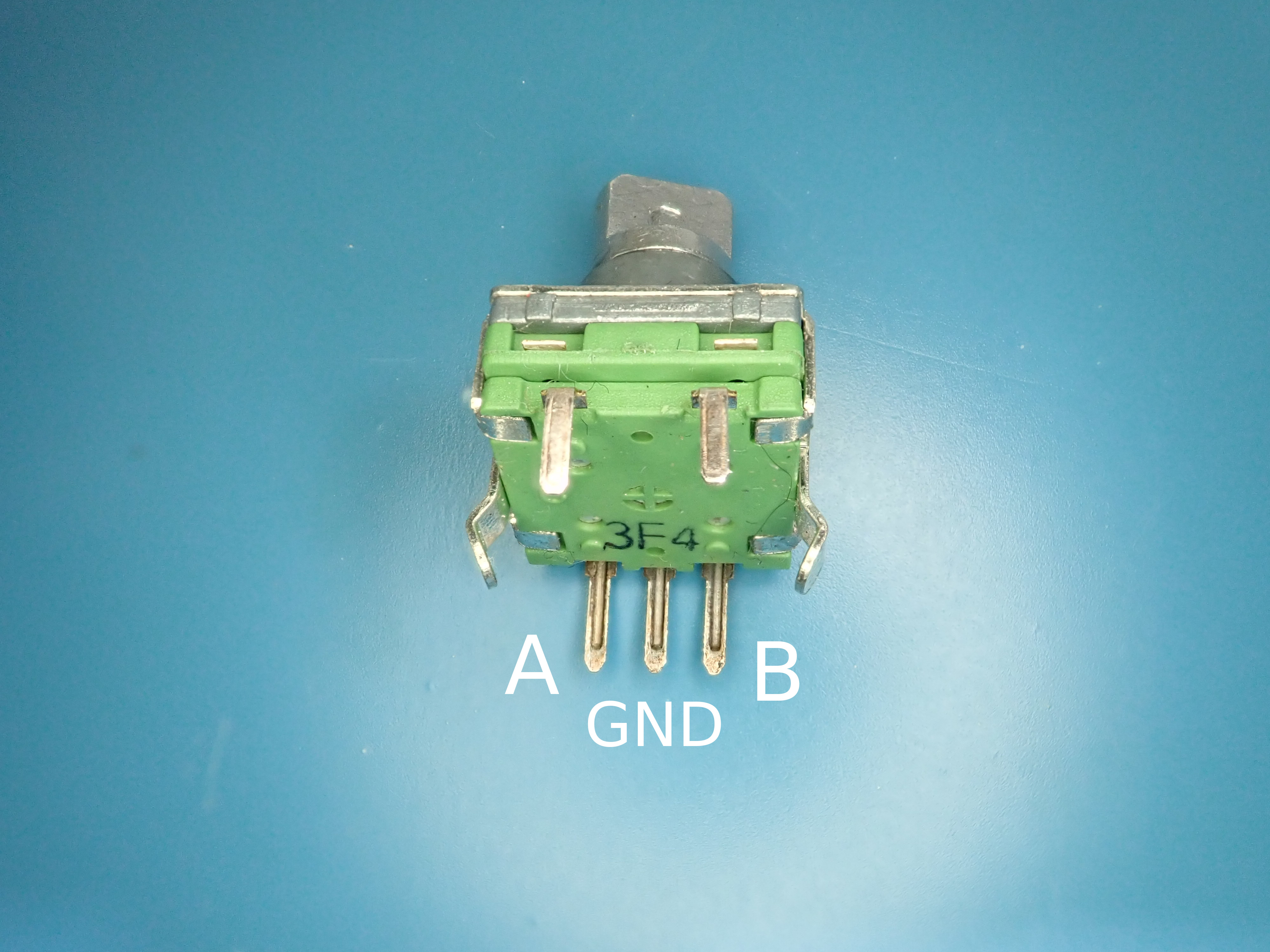
When connected to a microcontroller, pins {A, B} toggle between high and low as the shaft is rotated. The key concept is that one pin (A or B) will predictably change first depending on the direction the shaft is rotated.
| On some encoders, two more pins provide a switch that is toggled when the shaft is pushed. The rotary encoder shown above doesn’t have a switch, but the extra (fake) pins do add some stability on a breadboard. |
Detecting Rotations
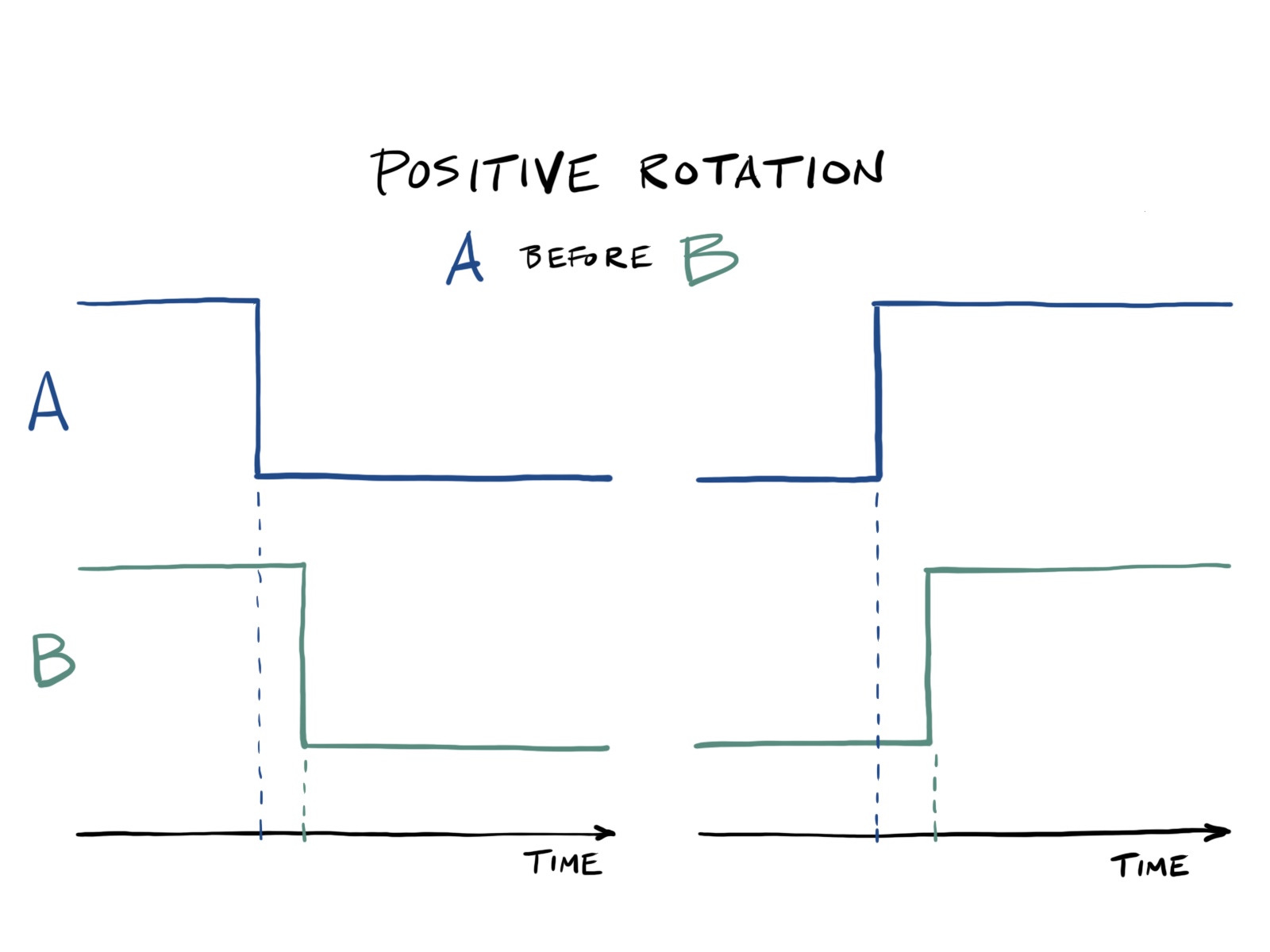
For a positive rotation (say clockwise), pin A will change before the B pin. This happens regardless of whether {A, B} are initially high or low. The two possible transitions that indicate a positive rotation are shown below.
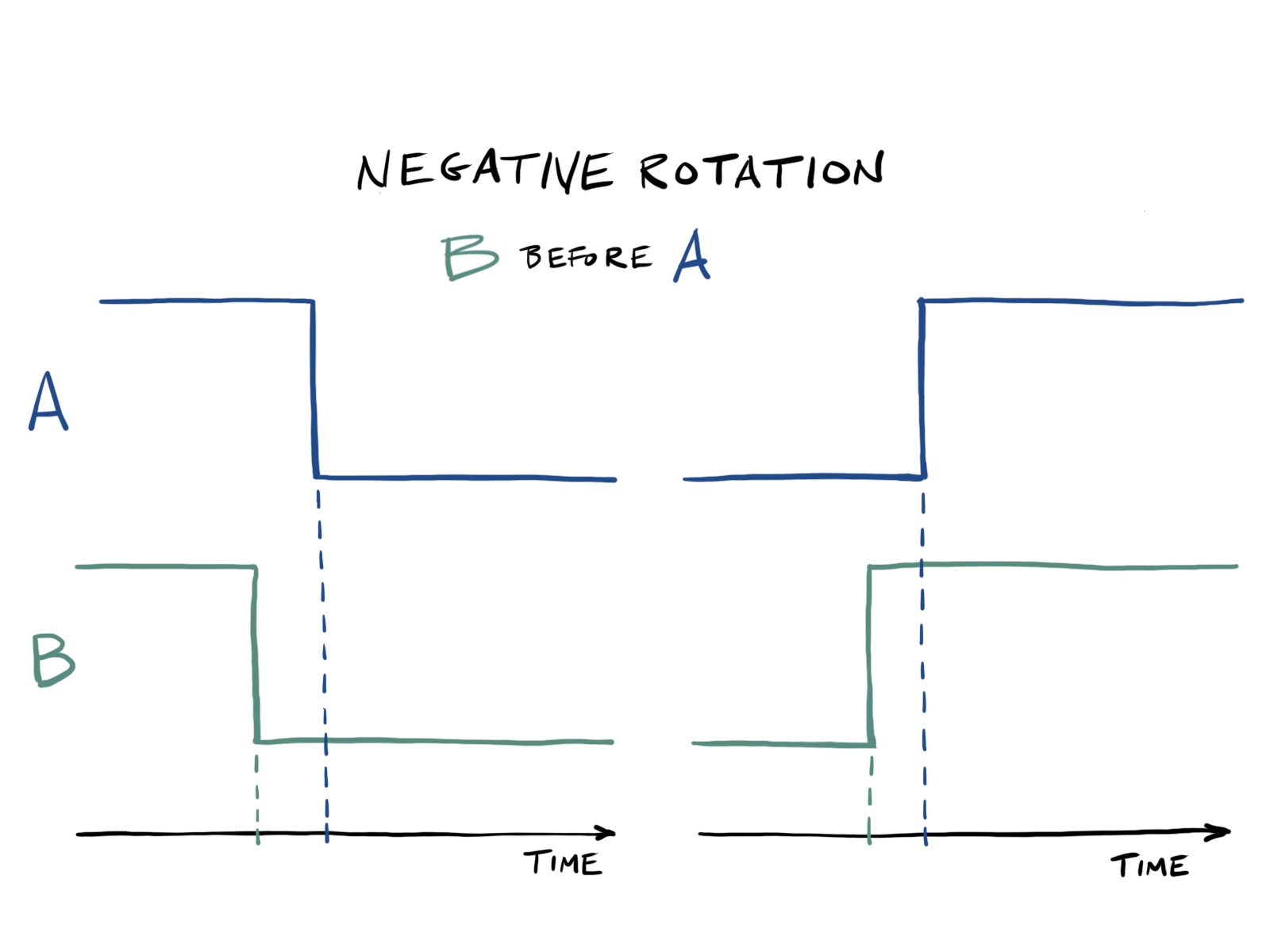
For a negative rotation (counterclockwise) the opposite is true, and pin B changes before pin A. Again, there are two possible transitions.
Interrupt Code
If an interrupt is enabled on pin A, then the direction of rotation can be determined based on pin B.
The following pseudocode captures the four transitions shown in the figures above.
if A is HIGH:
   if B is HIGH:
      rotation = NEGATIVE
   else:
      rotation = POSITIVE
else:
   if B is HIGH:
      rotation = POSITIVE
   else:
      rotation = NEGATIVE
This is implemented in the interrupt handler for PCINT1 in
rotenc.c.
/**
 * Handle PCINT1 interrupt.
 */
ISR(PCINT1_vect)
{
    uint8_t pinB = bit_is_set(ROTENC_PIN, ROTENC_B);
    char rotation;

    if (bit_is_set(ROTENC_PIN, ROTENC_A)) {
        rotation = pinB ? '-' : '+';
    } else {
        rotation = pinB ? '+' : '-';
    }

    putchar(rotation);
}
A sequence of + and - characters is displayed as the rotary
encoder is rotated clockwise and counterclockwise, respectively.